
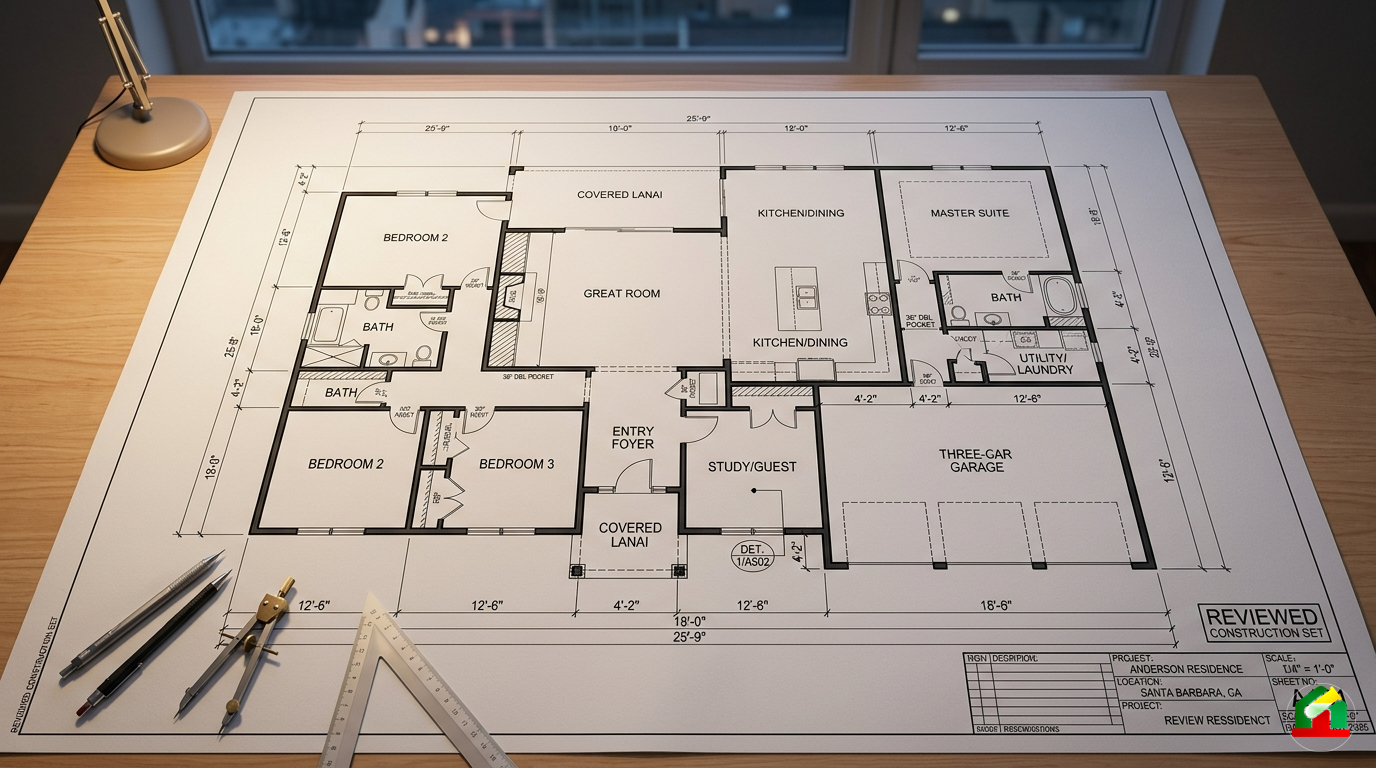

This is Part 3 of the Mastering AutoCAD Series on The Homes Lab Community. In Part 1 we built the foundational concepts. In Part 2 we toured the complete command library. Now we put it all together and draw something real. Follow along step by step — by the end of this article, you will have a complete, dimensioned, print-ready floor plan.
This is where everything changes.
Parts 1 and 2 gave you the tools and the vocabulary. Part 3 puts them in your hands and says — build something. We are going to draw a complete architectural floor plan from an absolute blank canvas to a fully dimensioned, annotated, print-ready drawing.
Every professional AutoCAD draughtsman, architect, and engineer started exactly here — staring at a blank screen, about to draw their first real plan. The process we follow in this article is not a simplified exercise. It is the actual professional workflow used on real projects — the same sequence of steps, the same layer discipline, the same layout setup that goes into drawings submitted for planning approval, construction, and client presentation.
Work through this article with AutoCAD open. Draw along as you read. By the time you reach the end, you will have produced something you can genuinely be proud of — and a workflow you can repeat on every project that follows.
Let us begin.
ðŸ The Floor Plan We Are Drawing
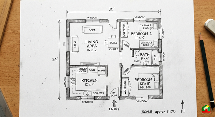
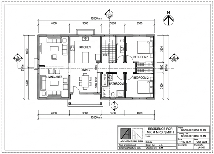
For this tutorial we are drawing a two-bedroom house floor plan — compact, clear, and realistic enough to practise every essential skill without becoming overwhelming.
The plan includes:
- External walls
- Internal partition walls
- Two bedrooms
- One bathroom
- An open-plan living and kitchen area
- Door openings with door swings
- Window openings
- Room labels and area annotations
- Full dimensioning
- A title block in Paper Space
Overall building dimensions:
- External footprint: 10,000mm wide Ã- 8,000mm deep
- Wall thickness: 150mm (internal) and 230mm (external)
- All dimensions in millimetres
💡 Tip: Always work in millimetres for architectural drawings in Kenya and most of the world. Never work in metres within the model — draw a 4,200mm room as 4,200 units, not 4.2. This keeps your dimension values clean, your text sizes manageable, and your file compatible with structural and MEP consultants.
âš™ï¸ STEP 1: Setting Up the Drawing File
Before drawing a single line, we configure the drawing environment. This is non-negotiable. Skipping setup is the single biggest mistake beginners make — and it causes problems that compound throughout the entire project.
1.1 — Open a New Drawing from a Template
Launch AutoCAD. At the Start Tab, click New and select the acadiso.dwt template — the standard metric template. This preloads sensible metric defaults for units, text, and dimensions.
âš ï¸ NB: Always start from acadiso.dwt for metric projects. Never start from a blank drawing with no template — you will spend time configuring settings that the template handles automatically.
1.2 — Set Your Units
Type UNITS and press Enter. In the dialog box, set:
- Length Type: Decimal
- Precision: 0 (whole millimetres — no decimal places needed for architectural work)
- Insertion Scale: Millimeters
Click OK.
1.3 — Set Your Drawing Limits
Type LIMITS and press Enter.
- Lower left corner:
0,0 - Upper right corner:
42000,29700
This sets a working area equivalent to an A3 sheet at 1:1 scale in millimetres — generous enough for our floor plan.
Then type ZOOM → A to zoom to the limits.
💡 Tip: Setting limits gives your grid a defined boundary and prevents you from accidentally drawing kilometres away from your actual geometry. It is a simple discipline that keeps your model space tidy.
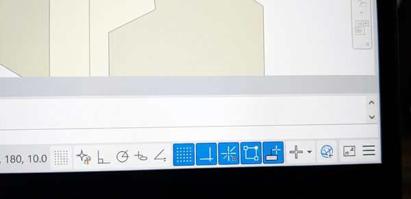
1.4 — Check Your Status Bar Settings
At the bottom of the screen, ensure the following are active:
| Toggle | State | Shortcut |
|---|---|---|
| OSNAP | ON | F3 |
| OTRACK | ON | F11 |
| DYNAMIC INPUT | ON | F12 |
| ORTHO | ON | F8 |
| GRID | ON | F7 |
Right-click the OSNAP button and ensure these snaps are running:
- ✅ Endpoint
- ✅ Midpoint
- ✅ Intersection
- ✅ Centre
- ✅ Perpendicular
âš ï¸ NB: Do not turn on every OSNAP simultaneously. Too many active snaps causes the cursor to jump unpredictably. The five listed above cover 95% of architectural drafting needs.
ðŸ-‚ï¸ STEP 2: Creating Your Layer Structure
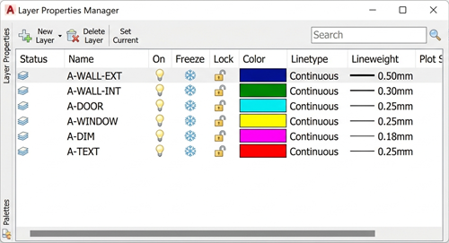
Layers are the organisational backbone of every professional AutoCAD drawing. Every object you draw must live on the correct layer — this controls its appearance, allows it to be isolated or hidden, and makes the drawing readable by anyone who opens it.
Type LAYER or LA to open the Layer Properties Manager.
Create the following layers:
| Layer Name | Colour | Linetype | Lineweight | Purpose |
|---|---|---|---|---|
A-WALL-EXT | White / 7 | Continuous | 0.50mm | External walls |
A-WALL-INT | White / 7 | Continuous | 0.30mm | Internal partition walls |
A-DOOR | Cyan / 4 | Continuous | 0.18mm | Door openings and swings |
A-WINDOW | Cyan / 4 | Continuous | 0.18mm | Window openings |
A-DIM | Green / 3 | Continuous | 0.18mm | Dimensions |
A-TEXT | Green / 3 | Continuous | 0.18mm | Room labels and notes |
A-GRID | Red / 1 | Centre | 0.13mm | Column and setting out grid |
A-HATCH | Grey / 8 | Continuous | 0.09mm | Hatch patterns and fills |
A-TITLEBLOCK | White / 7 | Continuous | 0.25mm | Title block in Paper Space |
DEFPOINTS | — | — | — | Auto-created — leave it |
âš ï¸ NB: Layer naming conventions vary by practice and country. The "A-" prefix stands for Architectural — in a multi-discipline project, structural layers use "S-", mechanical uses "M-", electrical uses "E-", and so on. Consistent naming makes collaboration seamless.
💡 Tip: Once you have created these layers, save this drawing as a template (.DWT file). Every future project starts from this template — with your layers, units, and settings already configured. This single habit saves hours across a professional career.
🧱 STEP 3: Drawing the External Walls
Now we draw. Set the current layer to A-WALL-EXT by clicking the layer dropdown in the Home tab and selecting it.
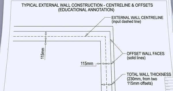
External walls are 230mm thick. We will draw them using the OFFSET method — the fastest and most accurate approach for wall construction in AutoCAD.
3.1 — Draw the External Wall Centrelines First
Type RECTANG or REC and press Enter.
- First corner: click anywhere in the drawing area — or type
0,0 - Second corner: type
@10000,8000
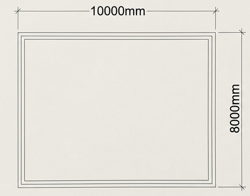
You now have a rectangle representing the external wall centreline of the building — 10,000mm wide and 8,000mm deep.
💡 Tip: Drawing to centrelines first and then offsetting to create wall thickness is the professional method. It keeps your setting-out dimensions clean and makes it easy to verify room sizes against your design brief.
3.2 — Offset to Create Wall Thickness
Type OFFSET or O.
- Offset distance:
115(half of 230mm wall thickness) - Select the rectangle
- Click outside the rectangle — this creates the outer face of the external wall
- Press Enter, type
OFFSETagain, distance115 - Select the rectangle again
- Click inside — this creates the inner face
You now have three rectangles:
- The original centreline rectangle
- The outer wall face
- The inner wall face
Delete the centreline rectangle — it has served its purpose. You are left with the two wall faces.
âš ï¸ NB: The two rectangles are closed polylines — each is a single object. This is why we drew them as rectangles rather than individual lines. We will use EXPLODE shortly to break them into individual wall segments for editing.
3.3 — Explode the Wall Rectangles
Type EXPLODE or X. Select both wall face rectangles and press Enter. Each rectangle is broken into four individual line segments — giving you independent control over each wall face line.
3.4 — Clean the External Wall Corners
The exploded lines extend past each other at the corners. Use FILLET with a radius of 0 to clean every corner to a sharp, precise meeting point.
Type FILLET or F:
- Type
R→ Enter → type0→ Enter (sets radius to zero) - Click two adjacent wall lines at a corner
- Repeat for all eight corners (four outer, four inner)
💡 Tip: Set FILLET radius to 0 once at the start of your drawing session — it stays at 0 until you change it. This makes corner cleaning a two-click operation throughout the entire drawing process.
🚪 STEP 4: Adding Internal Partition Walls
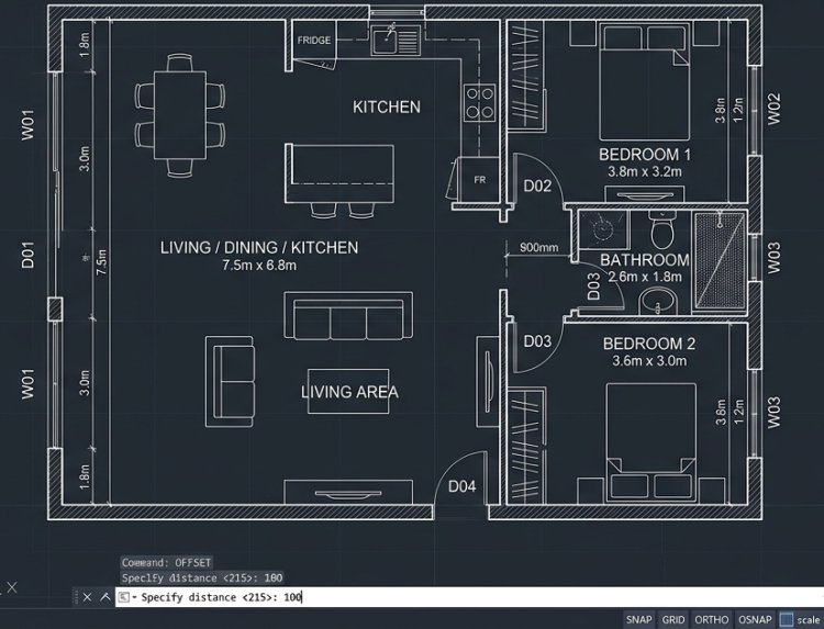
Set the current layer to A-WALL-INT. Internal walls are 150mm thick.
We will now divide the interior into rooms. Based on our two-bedroom house layout:
Internal wall positions (measured from inner face of external wall):
- Bedroom 1 / Bedroom 2 divider: 3,500mm from the left internal wall face — runs full depth
- Bedroom corridor / Living divider: 3,200mm from the bottom internal wall face — runs full width
- Bathroom partition: 1,800mm from the right internal wall face — runs 2,400mm deep from the top
4.1 — Drawing the Bedroom Divider Wall
Type LINE or L.
- First point: Snap to the inner face of the bottom external wall, 3,500mm from the left inner corner
- Type the coordinate or use OTRACK to track 3,500mm along the bottom inner wall line
- Next point: Track straight up with ORTHO on, snap to the inner face of the top external wall
- Press Enter
You have a single line representing the centreline of the bedroom divider wall.
Type OFFSET:
- Distance:
75(half of 150mm) - Offset the centreline left — first wall face
- Offset the centreline right — second wall face
- Delete the centreline
Clean the corners where the new wall meets the external walls using FILLET radius 0 or TRIM.
4.2 — Drawing the Living / Bedroom Corridor Divider
Repeat the same process:
Type LINE:
- First point: Snap to the inner face of the left external wall, 3,200mm up from the bottom inner corner
- Next point: Track straight right to the inner face of the right external wall
- Press Enter
Offset by 75mm each side, delete centreline, clean corners.
4.3 — Drawing the Bathroom Partition
Type LINE:
- First point: Snap to the inner face of the top external wall, 1,800mm from the right inner corner
- Next point: Track straight down 2,400mm with ORTHO on
- Press Enter
Offset by 75mm each side, delete centreline.
For the bathroom's second partition wall (closing the bathroom box):
Type LINE:
- From the bottom end of the previous wall centreline
- Track straight left to meet the bedroom divider wall
- Press Enter
Offset, delete centreline, clean all corners with FILLET or TRIM.
âš ï¸ NB: Every time a new wall meets an existing wall, you must clean the junction carefully. Use TRIM to remove wall lines that extend into the wall thickness of the intersecting wall — leaving clean T-junctions and L-junctions. Messy junctions are the most common sign of an unprofessional floor plan.
4.4 — Cleaning Wall Junctions
At every T-junction and L-junction, wall lines need to be trimmed cleanly. This is critical — no lines should overlap or extend through wall thickness.
Type TRIM or TR:
- Press Enter immediately (selects all objects as cutting edges)
- Click every line segment that extends into a wall junction
- Press Escape when done
Work systematically — go around every junction in the drawing. Zoom in close for precision. A clean, properly trimmed floor plan is what separates a professional drawing from a messy one.
💡 Tip: Zoom in very close (mouse wheel) when trimming wall junctions. What looks clean at full view often has tiny overlaps or gaps at high zoom. Clean at zoom level — your drawing will be perfect at print scale.
🚪 STEP 5: Adding Door Openings
Set the current layer to A-DOOR.
Doors require two things in a floor plan:
- The opening — a gap in the wall
- The door swing — an arc showing the door's swing radius
Our door schedule:
| Door | Location | Width |
|---|---|---|
| D01 | Front entrance — bottom external wall | 900mm |
| D02 | Bedroom 1 — corridor wall | 800mm |
| D03 | Bedroom 2 — corridor wall | 800mm |
| D04 | Bathroom — corridor wall | 700mm |
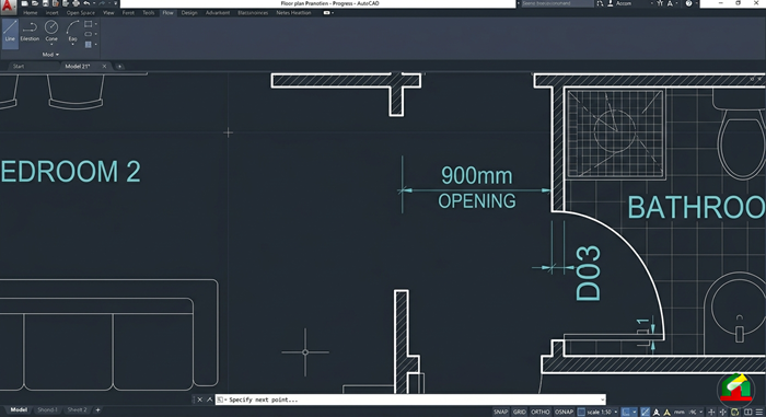
5.1 — Creating a Door Opening
For each door, we need to create a gap in the wall. We will work on the front entrance (D01) first.
Marking the opening position:
Type LINE — draw two short construction lines across both wall faces at the door opening edges:
- First line: at the start of the 900mm opening
- Second line: at the end of the 900mm opening
These mark the exact cut points.
Trimming the wall:
Type TRIM:
- Select the two construction lines as cutting edges
- Press Enter
- Click the wall lines between the two cut marks — both inner and outer wall face lines
- Press Escape
The opening appears. Delete the construction lines.
💡 Tip: For a 900mm door in a 230mm thick external wall, the gap in your drawing should be exactly 900mm measured between the jamb lines — not the rough opening. Consistency in door opening widths keeps your door schedule accurate.
5.2 — Drawing the Door Swing
The door swing is an arc from one edge of the opening, with a radius equal to the door width, sweeping to show the door's open position.
Type ARC or A:
- Start point: Snap to one jamb corner (where the door is hinged)
- Center: Same jamb corner (the hinge point)
Actually — use the Centre, Start, End method:
Type ARC → type C to select Centre option:
- Centre: Snap to the hinge jamb corner
- Start: Snap to the opposite jamb corner (the free edge of the door)
- End: Snap to a point on the wall face at 90° from the start
💡 Tip: Draw a temporary LINE from the hinge point perpendicular to the wall as a snap target for the arc end point — then delete it after the arc is placed. This ensures your door swing ends exactly at the wall face, which is the architectural convention.
Repeat this process for all four doors — adjusting positions and widths according to the door schedule.
🪟 STEP 6: Adding Window Openings
Set the current layer to A-WINDOW.
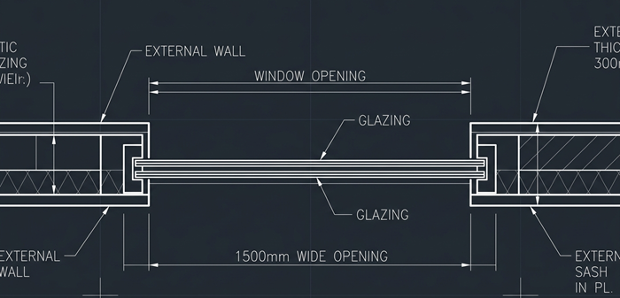
Windows are shown in floor plans as a gap in the wall with three parallel lines — representing the frame and glass line within the wall thickness.
Our window schedule:
| Window | Location | Width |
|---|---|---|
| W01 | Front external wall — Living area | 1,800mm |
| W02 | Front external wall — Bedroom 1 | 1,200mm |
| W03 | Rear external wall — Bedroom 2 | 1,200mm |
| W04 | Rear external wall — Bathroom | 600mm |
| W05 | Side external wall — Living area | 1,500mm |
6.1 — Creating a Window Opening
The process mirrors the door opening — mark the opening width with construction lines, trim the wall lines to create the gap.
6.2 — Drawing the Window Symbol
Within the window opening, draw three lines across the wall thickness:
- One line at the outer wall face (the outer frame line)
- One line at the inner wall face (the inner frame line)
- One line centred between them (the glass line)
Type LINE for each. Use OSNAP Midpoint to place the centre glass line precisely.
💡 Tip: Once you have drawn one window correctly, use COPY to place it at every other window opening — then just trim the wall gap to the correct width for each. This is dramatically faster than drawing each window from scratch.
6.3 — Creating a Window Block
Now that one window is drawn correctly, let us make it a reusable block.
Type BLOCK or B:
- Name:
WINDOW-1200 - Base point: Snap to the midpoint of one jamb line
- Select all three window lines
- Click OK
Now type INSERT or I — select WINDOW-1200, place it at each window opening, adjusting the rotation for windows on different walls.
💡 Tip: Create blocks for every standard element — doors, windows, sanitary fittings, furniture. A well-organised block library transforms your drawing speed entirely. Place once, reuse everywhere, edit the block definition and every instance updates instantly.
📠STEP 7: Dimensioning the Floor Plan
Set the current layer to A-DIM.
Before dimensioning, set up a dimension style that matches architectural standards.
7.1 — Creating a Dimension Style
Type DIMSTYLE or D. Click New and name it ARCH-100 (for 1:100 scale drawings).
Configure these settings:
Lines tab:
- Baseline spacing:
10 - Extension line offset from origin:
2 - Extension line beyond dim line:
3
Symbols and Arrows tab:
- Arrowheads: Architectural tick (the slash mark standard in architectural drawings)
- Arrow size:
3
Text tab:
- Text style: Create a new style using Arial or Romans font
- Text height:
3(appears as 3mm on the printed sheet at 1:100) - Text placement: Above dimension line
- Text alignment: Aligned with dimension line
Primary Units tab:
- Unit format: Decimal
- Precision:
0(whole millimetres) - Suffix: leave blank (no "mm" suffix — standard in architectural drawings)
Click OK and set ARCH-100 as the current dimension style.
âš ï¸ NB: Text height in the dimension style must be set relative to your drawing scale. At 1:100, a 3mm printed text height requires a model space text height of 300 (3 Ã- 100). However, if you are using annotative dimensions — which we recommend — AutoCAD handles this scaling automatically. We will set up annotative scaling in the Paper Space section below.
7.2 — Placing Dimensions
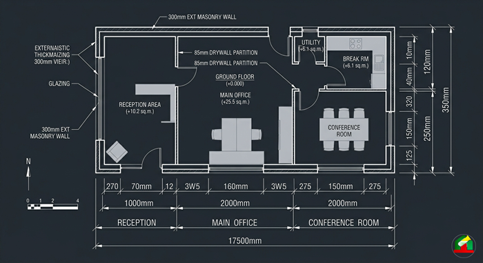
AutoCAD floor plans use three tiers of dimensions on each face of the building:
Tier 1 — Innermost: Individual room and opening dimensions (wall to wall, opening widths) Tier 2 — Middle: Grid or structural bay dimensions Tier 3 — Outermost: Overall building dimension
Start with the bottom face of the building.
Overall dimension:
Type DIMLINEAR or DLI:
- First extension line origin: Snap to the outer bottom-left corner of the external wall
- Second extension line origin: Snap to the outer bottom-right corner
- Place the dimension line below the building — approximately 2,000mm clear of the wall face
The overall dimension 10,000 appears.
Internal room dimensions:
Type DIMCONTINUE or DCO — continue from the last extension line:
- Pick the inner face of the first internal wall
- Pick the inner face of the next wall
- Continue across the full width
This chains all the internal dimensions in one continuous string.
💡 Tip: Always work from outside to inside when dimensioning — overall first, then subdivisions. This matches how contractors read and set out from drawings on site.
Repeat the dimensioning sequence on all four sides of the building, and add internal room-to-room dimensions across the plan.
ðŸ·ï¸ STEP 8: Adding Room Labels and Annotations
Set the current layer to A-TEXT.
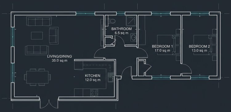
Every room in a floor plan needs:
- A room name
- A floor area (in square metres)
8.1 — Room Names
Type MTEXT or T. Draw a text box in the centre of each room and type the room name:
| Room | Label |
|---|---|
| Large bedroom | BEDROOM 1 |
| Smaller bedroom | BEDROOM 2 |
| Bathroom | BATHROOM |
| Main space | LIVING / DINING |
| Kitchen corner | KITCHEN |
Text height for room names: 300 (appears as 3mm at 1:100)
8.2 — Floor Areas
Calculate each room's floor area using MEASUREGEOM → Area → Object — select the inner boundary polyline of each room.
Add the area below the room name:
BEDROOM 112.60 m²
💡 Tip: Draw a closed polyline tracing the inner boundaries of each room — then use MEASUREGEOM to get the exact floor area. This is more accurate than manual calculation and updates automatically if the room size changes.
8.3 — Door and Window Tags
Using MLEADER — add reference tags to each door and window:
- Doors:
D01,D02,D03,D04 - Windows:
W01,W02,W03,W04,W05
These reference the door and window schedules that will live in the title block area.
8.4 — North Point
Every floor plan must have a north point.
Create a simple north arrow as a block — a circle with an arrow pointing north and the letter N — or INSERT a pre-made north point block if you have one in your library.
Place it in a clear area of the drawing, away from the plan geometry.
ðŸ-¨ï¸ STEP 9: Setting Up Paper Space for Printing
This is where your Model Space drawing becomes a professional, printable sheet. Click the Layout1 tab at the bottom of the screen — you enter Paper Space.
9.1 — Setting Up the Page
Right-click the Layout1 tab → Page Setup Manager → Modify.
Configure:
- Printer/Plotter: Select your printer or PDF driver
- Paper size: A1 (841mm Ã- 594mm) — standard for architectural floor plans
- Plot scale: 1:1 (Paper Space always plots at 1:1 — the scale is set in the viewport)
- Plot style table: monochrome.ctb (for black and white prints)
Click OK.
âš ï¸ NB: Always plot from Paper Space — never from Model Space. Plotting from Model Space is a shortcut that produces unprofessional, incorrectly scaled output. Paper Space gives you complete control over scale, sheet size, and multiple views on one sheet.
9.2 — Drawing the Title Block
Set the current layer to A-TITLEBLOCK.
Draw a border rectangle matching the printable area of your A1 sheet. Inside it, draw a title block panel in the bottom-right corner containing:
| Field | Content |
|---|---|
| Project Name | Two-Bedroom House |
| Drawing Title | Ground Floor Plan |
| Drawing Number | A-001 |
| Scale | 1:100 |
| Date | [Current Date] |
| Drawn By | [Your Name] |
| Revision | A |
Use LINE for the title block grid and MTEXT for the text fields.
💡 Tip: Save your title block as a block — or better yet, as a drawing template. A professional practice has a standard title block applied to every drawing sheet automatically. It takes time to set up once and saves time forever after.
9.3 — Creating and Scaling the Viewport
Delete the default viewport that AutoCAD created when you entered the layout (click it and press Delete).
Type VPORTS or -VPORTS — or simply type MV (Make Viewport):
Draw a rectangle on the sheet inside the title block border — this is your viewport frame. Double-click inside the viewport to enter Model Space through it.
Setting the viewport scale:
In the bottom-right corner of the status bar, find the viewport scale dropdown. Click it and select 1:100.
Now pan the view inside the viewport until your floor plan is centred and well-positioned on the sheet.
Double-click outside the viewport to return to Paper Space.
âš ï¸ NB: After setting the scale, lock the viewport to prevent accidental panning or zooming that would change the scale. Right-click the viewport border → Display Locked → Yes. A locked viewport is one of the most important Paper Space habits to develop.
9.4 — Setting Up Annotative Dimensions
If you set your dimension style to Annotative, you can now assign the annotation scale:
In Paper Space, click the viewport. In the Properties palette (Ctrl+1), find Annotation Scale and set it to 1:100.
Your dimensions, text, and annotations will now display at the correct size — 3mm text height on the printed sheet — regardless of the model space drawing scale.
💡 Tip: Annotative scaling is one of AutoCAD's most powerful features for professional drawing production. Once set up correctly, you never manually calculate text heights or dimension scale factors again. We will explore annotative objects in full depth in a later part of this series.
ðŸ-¨ï¸ STEP 10: Plotting Your Drawing
You are ready to print.
Type PLOT or press Ctrl+P. The Plot dialog opens.
Verify:
- Page setup: Your A1 configuration
- Plot area: Layout
- Plot scale: 1:1
- Plot style table: monochrome.ctb
- Plot offset: Centre the plot on the paper
Click Preview — your drawing should appear exactly as it will print. Confirm the floor plan is correctly scaled, centred, and the title block is complete.
Click OK to plot.
âš ï¸ NB: Always preview before plotting. A single Print Preview click catches misaligned viewports, wrong scales, missing layers, and cropped title blocks — before wasting paper or submitting the wrong drawing to a client.
✅ Your Completed Floor Plan — A Checklist
Before considering any floor plan complete and ready for issue, run through this checklist:
Geometry:
- ✅ External walls correct thickness and fully closed
- ✅ Internal walls correct thickness, all junctions clean
- ✅ All door openings correct width with door swings drawn
- ✅ All window openings correct width with window symbols drawn
- ✅ No overlapping or duplicate lines (run OVERKILL)
- ✅ No open polylines or gaps in wall boundaries
Layers:
- ✅ All walls on correct wall layers
- ✅ All doors on A-DOOR layer
- ✅ All windows on A-WINDOW layer
- ✅ All dimensions on A-DIM layer
- ✅ All text on A-TEXT layer
- ✅ Nothing drawn on Layer 0
Annotation:
- ✅ All rooms labeled with name and area
- ✅ All doors tagged with reference numbers
- ✅ All windows tagged with reference numbers
- ✅ North point placed
- ✅ Full dimension string on all four sides of building
- ✅ Internal room dimensions complete
Paper Space:
- ✅ Viewport scale set to 1:100 and locked
- ✅ Title block complete with all fields filled
- ✅ Sheet border correctly positioned
- ✅ Print preview checked
File:
- ✅ PURGE run to remove unused definitions
- ✅ AUDIT run to check file health
- ✅ File saved with a clear, professional name
💡 Tip: Develop the habit of running this checklist before issuing every single drawing — whether to a client, contractor, or colleague. Professionals who check their work before sending it build reputations for quality. Those who do not, eventually wish they had.
🚀 Final Thoughts
A floor plan is the most fundamental document in construction and design. Every building that has ever been built started with one. Now you know how to produce one — professionally, accurately, and to a standard that can be submitted, shared, and built from.
The workflow you followed today — setup, layers, external walls, internal walls, doors, windows, dimensions, annotations, Paper Space, print — is the same workflow used by professional architects and draughtsmen on real projects. You did not follow a simplified tutorial. You followed the real process.
Keep this drawing. Refine it. Add furniture. Add a second floor. Try a different house type. Every drawing you produce from here builds on the foundation you laid today.
Follow the complete Mastering AutoCAD Series on The Homes Lab Community — and share it with every student, designer, and construction professional who wants to master the most important drafting tool in the industry.