
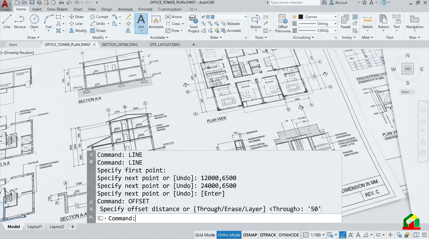

This is Part 2 of the Mastering AutoCAD Series on The Homes Lab Community. If you are just joining us, start with Part 1: The Concepts Every Beginner Must Know to build the foundation before diving into commands. This series is designed to take you from beginner to professional — one part at a time.
In Part 1, we established the mindset, the interface, and the intellectual framework behind AutoCAD. Now we get to work.
This article is your complete command reference — a guided tour through over 130 AutoCAD commands, grouped by purpose, explained in plain language, and illustrated with real-world context. This is not a dry list of keywords. Every command here is a tool with a personality, a prompt pattern, and a specific job to do. Learn them well and your drafting speed, accuracy, and confidence will transform entirely.
There is a reason experienced AutoCAD users seem to work at a different speed from everyone else. It is not talent — it is command fluency. They have had so many conversations with the Command Line that the responses are automatic. That fluency is exactly what this article builds.
Keep this page bookmarked. You will return to it.
ðŸ-Šï¸ SECTION 1: Drawing Commands — Laying Down Lines, Shapes & Curves
Every AutoCAD project begins here. These are the tools that put geometry on screen — lines, curves, shapes, fills, and construction aids. Master these and you have the vocabulary to describe virtually any built form.
LINE — The Most Fundamental Command
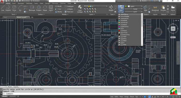
Type LINE or simply L and press Enter. The Command Line immediately asks:
"Specify first point:"
Click anywhere or type coordinates. Then it asks:
"Specify next point or [Undo]:"
Keep clicking to add segments. Type C to close the shape back to the first point. Press Enter or Escape to finish.
💡 Tip: Every LINE segment is an independent object. If you need connected segments that behave as one object — for walls, boundaries, or paths — use PLINE (Polyline) instead.
CIRCLE — Multiple Ways to Define a Round
Type CIRCLE or C. The default prompt asks for a centre point and a radius. But watch the Command Line carefully — it also offers:
- 2P — define the circle by two points on its diameter
- 3P — define it by three points on its circumference
- Ttr — tangent, tangent, radius — draws a circle tangent to two existing objects
💡 Tip: The Ttr option is incredibly useful when fitting a circle between two walls or two lines. Instead of calculating the centre manually, AutoCAD finds it for you.
ARC — Curves with Precision
Type ARC or A. The default sequence asks for a start point, a second point, and an end point. But ARC offers extensive sub-options:
- Center — define the arc from its centre outward
- Angle — specify the included angle of the arc
- Length — define the chord length
- Direction — control the tangent direction at the start point
âš ï¸ NB: AutoCAD always draws arcs counter-clockwise by default. If your arc appears to curve the wrong way, either reverse your point selection order or use the Direction option to flip it.
RECTANG — Rectangles in Seconds
Type RECTANG or REC. It asks for a first corner, then the opposite corner. But before placing the first corner, you can activate powerful sub-options:
- Chamfer — adds cut corners at a specified distance
- Fillet — adds rounded corners at a specified radius
- Width — gives the rectangle's boundary a visible line width
- Elevation / Thickness — for 3D work
💡 Tip: Use relative coordinates for the second corner to control exact dimensions. For example, after placing the first corner, type
@3000,2000to draw a rectangle exactly 3000 units wide and 2000 units tall — instantly, without measuring.
POLYGON — Regular Shapes, Any Number of Sides
Type POLYGON or POL. First it asks:
"Enter number of sides:"
Then it asks whether you want to define the polygon by a circumscribed circle (points touch the circle) or an inscribed circle (sides touch the circle), followed by the centre point and radius.
💡 Tip: POLYGON is perfect for drawing bolt heads, nuts, hexagonal columns, and any regular geometric shape — in seconds, with perfect symmetry.
ELLIPSE — Precise Oval Geometry
Type ELLIPSE or EL. It asks for one axis endpoint, then the other end of the same axis, then:
"Specify distance to other axis or [Rotation]:"
The Rotation option defines the ellipse by rotating a circle around the first axis — useful for isometric drawings.
SPLINE — Freeform Curves Through Precise Points
Type SPLINE or SPL. It asks for fit points one after another, drawing a smooth curve through each. Press Enter when done, then define the start and end tangent directions.
âš ï¸ NB: Splines are mathematically complex curves. They are perfect for organic shapes — contour lines on site plans, freeform furniture profiles, or landscape features — but avoid overusing them in technical drawings where simple arcs will do.
PLINE — The Polyline, Your Most Versatile Drawing Tool
Type PLINE or PL. A polyline is a chain of connected line and arc segments that behaves as a single object. The prompt walks you through each segment, offering:
- Arc — switch to arc mode mid-polyline
- Width — assign a start and end width to each segment
- Close — close back to the start point
💡 Tip: Draw walls, road boundaries, plot outlines, and floor plan perimeters as polylines. Because they are single objects, you can select, move, and measure the entire shape with one click.
HATCH — Filling Areas with Patterns
Type HATCH or H. Click inside any enclosed area and AutoCAD detects the boundary automatically. The Hatch palette opens, offering:
- Pattern type — ANSI, ISO, and custom patterns
- Scale — how dense or spread the pattern appears
- Angle — rotation of the pattern
- Associativity — the hatch updates automatically if the boundary changes
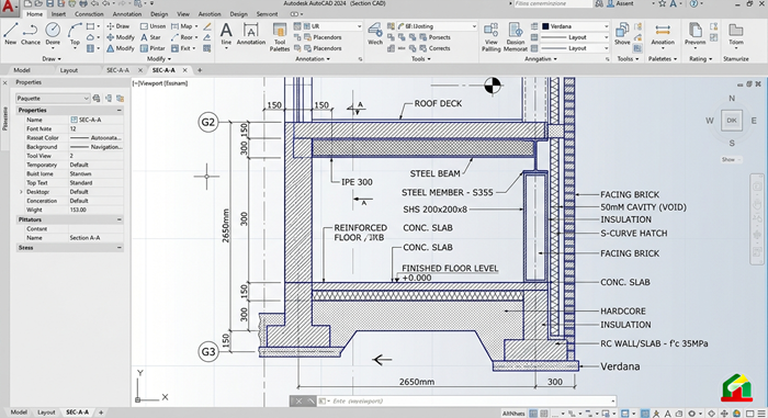
💡 Tip: In architectural drawings, use HATCH to show materials in section — diagonal lines for concrete, dots for insulation, cross-hatching for steel. It makes sections instantly readable.
GRADIENT — Smooth Colour Fills
Type GRADIENT. Works exactly like HATCH but fills areas with smooth colour transitions — one colour or two. Useful for presentation drawings and renders within AutoCAD.
XLINE — Infinite Construction Lines
Type XLINE or XL. Creates a line that extends infinitely in both directions through a point at any angle. Sub-options include:
- Hor — perfectly horizontal
- Ver — perfectly vertical
- Ang — at a specified angle
- Bisect — bisects the angle between two lines
- Offset — parallel to an existing line at a distance
💡 Tip: XLINE is the drafter's set square. Use it to establish axis lines, grid lines, and projection lines across your drawing before placing actual geometry. Delete them when done — they are construction aids, not final geometry.
RAY — Half-Infinite Construction Line
Type RAY. Like XLINE but extends in only one direction from a start point. Useful for projection work where you only need guidance in one direction.
POINT — Precise Location Markers
Type POINT or PO. Places a point object at a specified coordinate. By default it appears as a tiny dot, but changing the PDMODE system variable transforms it into a visible cross, circle, or other marker.
DONUT — Filled Rings and Solid Circles
Type DONUT or DO. It asks for an inside diameter, an outside diameter, and a centre point — then keeps repeating the centre point prompt so you can place multiple donuts in one command. Set inside diameter to 0 for a solid filled circle.
HELIX — Spiral and Spring Geometry
Type HELIX. Prompts ask for base radius, top radius, base centre point, height, and number of turns. Creates a 3D spiral path — perfect as the foundation for sweeping spring and thread geometry in 3D models.
3DPOLY — 3D Polylines
Type 3DPOLY. Like PLINE but accepts full 3D coordinates (X, Y, and Z) for each point. Useful for drawing paths and edges in 3D space that follow non-planar routes.
📠SECTION 2: Precision Commands — Grids, Snaps & Measurements
Drawing in AutoCAD without precision tools is like building a house without a level. These commands transform the drawing environment into an instrument of exact measurement — ensuring every point, line, and angle is exactly where it needs to be.
UNITS — Setting Your Measurement Standard
Type UNITS. A dialog opens to set:
- Length type — Decimal, Architectural, Engineering, or Fractional
- Precision — decimal places displayed
- Insertion scale — millimetres, metres, inches, etc.
For command-line control, use -UNITS to step through the same settings as text prompts.
âš ï¸ NB: Always set UNITS before drawing anything in a new file. A mismatch between drawing units and insertion scale causes catastrophic scaling errors when files are combined — a 150mm wall suddenly appears as 150 metres.
LIMITS — Defining Drawing Boundaries
Type LIMITS. Set a lower-left and upper-right boundary for your drawing area. While many professionals ignore this command in daily work, it is useful for controlling the grid display area and establishing a defined working zone in large drawings.
GRID — Visual Reference Matrix
Type GRID or press F7 to toggle. Displays a dot or line matrix across the drawing area as a visual reference. The grid spacing can be customised — type GRID and enter a spacing value.
💡 Tip: Grid is a visual aid only — it does not affect snapping unless SNAP is also turned on. Many professionals turn the grid off once they are comfortable navigating by coordinates alone.
SNAP — Locking the Cursor to Intervals
Type SNAP or press F9. Forces the cursor to jump to invisible increment intervals — useful for schematic drawings where everything aligns to a fixed grid.
ORTHO — Perfectly Straight Lines Every Time
Type ORTHO or press F8. When Ortho is on, the cursor can only move horizontally or vertically. This is one of the most-used toggles in architectural and engineering drafting — walls, grids, and structural elements almost always run orthogonally.
âš ï¸ NB: Ortho and Polar Tracking cannot both be active simultaneously. Turning one on automatically disables the other.
POLAR — Angular Tracking Guide
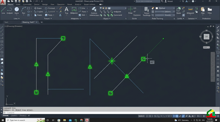
Type POLAR or press F10. When the cursor approaches a user-defined angle increment — 45°, 30°, 15°, etc. — a dotted tracking line appears, snapping the cursor to that angle with a distance readout. Perfect for drawing diagonal elements at precise angles without typing coordinates.
OSNAP — Object Snap, the Heart of Precision
Type OSNAP or press F3 to toggle. Object Snap makes specific geometric points magnetic — the cursor snaps exactly to:
| Snap Code | What It Snaps To |
|---|---|
| END | Endpoint of a line or arc |
| MID | Midpoint of a line or arc |
| INT | Intersection of two objects |
| CEN | Centre of a circle or arc |
| PER | Perpendicular point on a line |
| TAN | Tangent point on a circle |
| NEA | Nearest point on any object |
| QUA | Quadrant points of a circle (0°, 90°, 180°, 270°) |
| INS | Insertion point of a block or text |
âš ï¸ NB: Running too many Object Snaps simultaneously causes the cursor to snap to unintended points, slowing you down and introducing errors. Set only the snaps you actively need for each task — and turn off the rest.
💡 Tip: Hold Shift and right-click anywhere in the drawing area to access a one-time Object Snap override menu — perfect for grabbing a snap type you do not have running permanently.
OTRACK — Object Snap Tracking
Type OTRACK or press F11. Extends Object Snap by projecting alignment paths from snapped points — allowing you to place a new point aligned to multiple existing geometry points simultaneously, without drawing construction lines.
💡 Tip: OTRACK combined with OSNAP is one of the most powerful precision combinations in AutoCAD. Hover over a snap point to acquire it, move the cursor, and the tracking path appears automatically. Use it to place room centrelines, column grid intersections, and door swing centres with zero guesswork.
DIST — Measuring Distance and Angle
Type DIST or DI. Pick two points and the Command Line instantly reports:
- Distance between the points
- Delta X and Delta Y
- Angle from horizontal
💡 Tip: Use DIST constantly to verify your geometry as you draw. Do not wait until the drawing is complete to discover a wall is 50mm too short.
MEASUREGEOM — The All-in-One Measurement Tool
Type MEASUREGEOM or MEA. This is the Swiss Army knife of measurement. From its prompt loop, choose:
- Distance — between two points
- Radius — of an arc or circle
- Angle — between two lines or three points
- Area — of a closed boundary or object
- Volume — of a 3D solid
All results appear dynamically at the cursor tip and in the Command Line.
AREA — Calculating Surface Areas
Type AREA. Pick an object or click a series of boundary points to calculate the enclosed area. Results appear in the Command Line. Use the Add and Subtract modes to calculate net areas — useful for computing floor areas with openings deducted.
💡 Tip: For floor area calculations in architectural drawings, draw a closed polyline around the space boundary and use
MEASUREGEOM→Area→Object— then select the polyline. Instant, accurate floor area every time.
ID — Identifying Exact Coordinates
Type ID. Pick any point and the Command Line reports its exact X, Y, and Z coordinates. Essential for verifying survey coordinates, column grid origins, and setting out points.
LIST — Full Object Property Report
Type LIST or LI. Select any object and press Enter. A text window opens showing every property of that object — layer, colour, linetype, length, area, coordinates, and more.
DIVIDE — Splitting Objects into Equal Parts
Type DIVIDE or DIV. Select an object and specify the number of equal segments. AutoCAD places point markers (or blocks) at each division. The object itself is not cut — only marked.
💡 Tip: Use DIVIDE to evenly space columns along a beam, plant trees along a road, or mark equal intervals on a facade — without any manual calculation.
MEASURE — Spacing Objects at Fixed Intervals
Type MEASURE or ME. Similar to DIVIDE, but instead of a number of segments, you specify a fixed interval distance. AutoCAD places markers at that spacing from one end of the object to the other.
âœ‚ï¸ SECTION 3: Modify Commands — Editing & Transforming Geometry
The ability to edit non-destructively is one of AutoCAD's greatest strengths. These commands let you transform, refine, duplicate, and clean up geometry with speed and precision — without ever starting over.
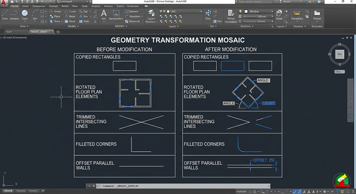
MOVE — Relocating Objects
Type MOVE or M. Select objects, press Enter, specify a base point, then a destination point. Use relative coordinates (@500,0) to move an exact distance and direction.
💡 Tip: For precise moves, always snap the base point to a known geometric point — like a corner or midpoint — rather than clicking empty space. This gives you full control over where the object lands.
COPY — Duplicating Objects
Type COPY or CO. Works exactly like MOVE but leaves the original in place. After specifying the base point, you can keep placing copies by clicking multiple destination points — without restarting the command.
Watch for the Array sub-option in the prompt — it builds a linear pattern of copies in one step.
ROTATE — Turning Objects Around a Pivot
Type ROTATE or RO. Select objects, specify a base point (the pivot), then enter a rotation angle. Positive angles rotate counter-clockwise. Negative angles rotate clockwise.
The Reference sub-option is particularly powerful — it lets you rotate an object from its current angle to a target angle by referencing existing geometry, without knowing the exact rotation value.
SCALE — Resizing Objects
Type SCALE or SC. Select objects, specify a base point, then enter a scale factor. A factor of 2 doubles the size. A factor of 0.5 halves it.
The Reference sub-option allows scaling by comparing a known existing length to a desired length — AutoCAD calculates the factor automatically.
âš ï¸ NB: Scaling affects ALL dimensions of the selected objects uniformly. If you need to stretch in only one direction, use STRETCH instead.
MIRROR — Flipping Geometry
Type MIRROR or MI. Select objects, then define a mirror line with two points. AutoCAD asks:
"Erase source objects? [Yes/No]:"
Type N to keep the original (creating a reflected copy) or Y to flip it entirely.
💡 Tip: Mirror is indispensable for symmetrical floor plans — draw one half of a building perfectly, then mirror it to create the other half instantly. Saves enormous amounts of time on symmetrical structures.
STRETCH — Lengthening and Reshaping
Type STRETCH or S. Must be used with a crossing window selection — only vertices inside the crossing window are moved; everything outside stays fixed. This makes it the perfect tool for lengthening a room, extending a wall, or adjusting a door opening width without disturbing the rest of the drawing.
TRIM — Cutting Objects at Boundaries
Type TRIM or TR. Select cutting edges first, press Enter, then click the portions of lines or arcs you want to remove. AutoCAD cuts precisely at the intersection.
💡 Tip: Press Enter immediately when TRIM asks for cutting edges — this selects ALL visible objects as potential cutting edges. Then just click whatever you want trimmed. This two-keystroke method (
TR→Enter→ click) is one of the fastest editing sequences in AutoCAD.
âš ï¸ NB: Hold Shift while using TRIM to temporarily switch to EXTEND — and vice versa. This saves constantly switching between the two commands.
EXTEND — Lengthening Objects to a Boundary
Type EXTEND or EX. Select boundary edges first, press Enter, then click the objects to extend. They stretch to meet the boundary exactly.
OFFSET — Creating Parallel Copies
Type OFFSET or O. Specify an offset distance, select an object, then click which side to offset toward. AutoCAD creates a perfect parallel copy at the specified distance.
💡 Tip: OFFSET is one of the most-used commands in architectural drafting. Draw one wall line, then OFFSET it by the wall thickness to create the second face — instantly, perfectly parallel, exactly the right distance apart.
FILLET — Rounded Corners
Type FILLET or F. Set a radius first (type R at the prompt, then enter the value), then select two lines. AutoCAD trims them to meet at a perfect arc of the specified radius.
Setting the radius to 0 creates a clean sharp corner — trimming two lines to meet exactly at their intersection without any rounding. This is one of the fastest corner-cleaning tricks in AutoCAD.
CHAMFER — Angled Cut Corners
Type CHAMFER or CHA. Similar to FILLET but creates a straight diagonal cut instead of a curve. Set two distances (or a distance and angle), then select two lines.
BREAK — Removing a Portion of an Object
Type BREAK or BR. Select an object, pick the first break point, then the second. AutoCAD erases the portion between the two points.
Use BREAK AT POINT to split an object at a single point into two separate objects without removing any geometry.
JOIN — Merging Objects into One
Type JOIN or J. Select a source object, then additional objects to merge into it. Connected lines, arcs, and polylines are welded into a single object.
💡 Tip: Use JOIN after importing DXF files or tracing over PDFs — imported geometry is often broken into fragments. JOIN reconnects them into clean, usable polylines.
LENGTHEN — Adjusting Object Length
Type LENGTHEN or LEN. Select an object to see its current length, then choose from:
- Delta — add or subtract a fixed amount
- Percent — change by a percentage of current length
- Total — set an absolute final length
- Dynamic — drag the endpoint interactively
ALIGN — Moving and Rotating in One Step
Type ALIGN. Select objects, then define pairs of source and destination points. AutoCAD moves and rotates the selection to align the source points with the destination points — in both 2D and 3D. Extremely powerful for aligning imported blocks, survey data, or external references.
OVERKILL — Removing Duplicate Geometry
Type OVERKILL. Select objects and AutoCAD automatically finds and deletes duplicate lines, overlapping segments, and redundant geometry. Essential for cleaning up traced drawings or imported files.
REVERSE — Flipping Object Direction
Type REVERSE. Flips the direction of a line or polyline — swapping the start and end points. Critical when using linetypes that have directional symbols (arrows, ticks) that need to face a specific way.
BLEND — Smooth Curve Connection
Type BLEND. Select two open curves or lines end-to-end and AutoCAD creates a smooth spline connecting them with tangent continuity. Perfect for joining interrupted contour lines or freeform profile curves.
REVCLOUD — Revision Bubbles
Type REVCLOUD. Draws a cloud-shaped boundary — the universal draughting symbol for a revised area. Set the arc length and draw freehand around the revised portion of your drawing.
💡 Tip: Use REVCLOUD on a dedicated "Revision" layer so revision clouds can be frozen or turned off on final issued drawings.
WIPEOUT — Masking Areas
Type WIPEOUT. Draw a polygon boundary and AutoCAD places a blank mask over everything behind it — without deleting any geometry. Used to create clean white spaces behind text blocks, title banners, and annotation tables.
🔠SECTION 4: Arrays, Polylines & Smart Object Selection
When repetition, pattern, and complex object management come into play, these commands take over. They are the difference between drawing something once and drawing it a hundred times.
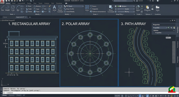
ARRAYRECT — Rectangular Arrays
Type ARRAYRECT. Select objects, then define:
- Number of columns and rows
- Column spacing and row spacing
AutoCAD shows a live preview as you adjust values. The result is an associative array — meaning you can edit the spacing and count even after creation.
💡 Tip: Use ARRAYRECT for repetitive building elements — window grids on a facade, column grids on a structural plan, brick coursing on a wall elevation, or parking bays in a car park layout.
ARRAYPOLAR — Circular Arrays
Type ARRAYPOLAR. Select objects, specify a centre point, number of items, and the angle to fill (360° for a full circle). Perfect for bolts around a flange, columns around a rotunda, or radial seating layouts.
ARRAYPATH — Arrays Along a Curve
Type ARRAYPATH. Select objects, then select a path curve (line, arc, spline, or polyline). Specify the number of items or the spacing between them. Items can be aligned to follow the path's direction automatically.
💡 Tip: ARRAYPATH is perfect for planting trees along a curved road, placing light poles along a winding path, or spacing balusters along a curved staircase handrail.
ARRAYEDIT — Editing Associative Arrays
Type ARRAYEDIT. Select an existing associative array and modify its parameters — count, spacing, path, or individual items — without recreating it from scratch.
EXPLODE — Breaking Compound Objects Apart
Type EXPLODE or X. Breaks blocks, polylines, hatches, arrays, and dimensions into their individual component objects.
âš ï¸ NB: Exploding a block destroys its definition link — you can no longer update all instances by editing the block. Only explode when absolutely necessary, and never explode blocks that you may need to update later.
PEDIT — Editing Polylines
Type PEDIT or PE. Select a polyline (or convert a line to one) and access a full sub-menu:
- Join — weld connected lines into one polyline
- Width — set a uniform or tapered width
- Fit / Spline — curve-fit the polyline
- Reverse — flip the direction
- Edit Vertex — move, insert, or delete individual vertices
💡 Tip: Use PEDIT → Join to connect traced boundary lines into a single closed polyline — essential before calculating areas or using the boundary as a hatch perimeter.
MATCHPROP — The Format Painter
Type MATCHPROP or MA. Select a source object, then destination objects. All properties — layer, colour, linetype, lineweight — are copied from source to destination instantly.
💡 Tip: MATCHPROP is one of the fastest ways to fix incorrectly layered geometry. Instead of opening the Properties palette and manually changing settings, simply paint the correct properties from a correctly layered object.
PROPERTIES — Full Object Property Control
Type PROPERTIES or PR, or press Ctrl+1. Opens the Properties palette showing every attribute of selected objects — layer, colour, linetype, coordinates, dimensions — all editable directly.
GROUP — Named Selection Sets
Type GROUP or G. Combines selected objects into a named group — they can be selected as one with a single click but remain individual objects (unlike blocks). Useful for managing clusters of objects you repeatedly select together.
QSELECT — Filter-Based Selection
Type QSELECT. Opens a dialog where you build selection criteria — select all circles on a specific layer, all text above a certain height, or all red lines in the drawing. AutoCAD selects every matching object instantly, regardless of drawing size.
💡 Tip: QSELECT is a massive time-saver in large, complex drawings. Instead of hunting for objects manually, describe what you want and AutoCAD finds them all.
📠SECTION 5: Annotation Commands — Text, Dimensions & Leaders
A drawing without annotation is incomplete. These commands give your geometry a voice — communicating sizes, materials, notes, and references to everyone who reads the drawing.
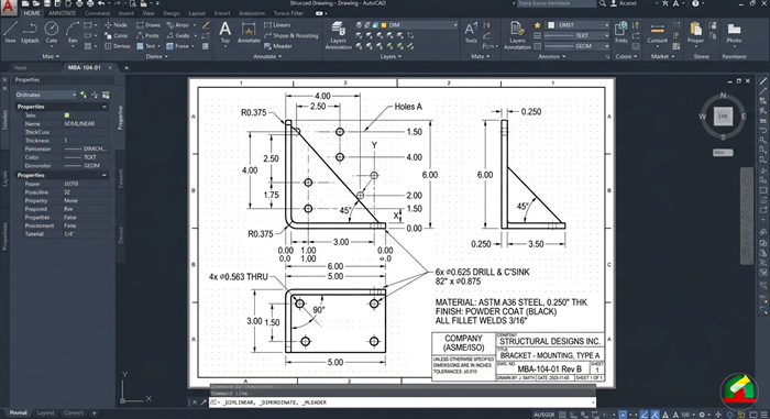
TEXT — Single Line Text
Type TEXT or DT. Specify a start point, text height, and rotation angle. Type your text directly on the drawing. Press Enter to move to the next line or Escape to finish.
💡 Tip: Use TEXT for short labels — room names, grid references, spot levels. For longer notes and paragraphs, always use MTEXT instead.
MTEXT — Multi-Line Text Editor
Type MTEXT or MT or T. Draw a text box boundary on the drawing and an in-place text editor opens. Supports:
- Multiple paragraphs and line spacing
- Bold, italic, underline formatting
- Bulleted and numbered lists
- Stacked fractions (e.g. 1/2 displayed as a fraction)
- Column layouts
âš ï¸ NB: Always use MTEXT for specification notes, general arrangement notes, and any text that may need to wrap or be edited later. Single-line TEXT is rigid and difficult to manage for longer content.
DIMLINEAR — Horizontal and Vertical Dimensions
Type DIMLINEAR or DLI. Pick two extension line origins (the points being measured), then click to place the dimension line. Sub-options include:
- Mtext — edit the dimension text before placing
- Text — replace the measured value with custom text
- Angle — rotate the dimension text
- Horizontal / Vertical — force a specific orientation
DIMALIGNED — Dimensions Along Any Angle
Type DIMALIGNED or DAL. Identical to DIMLINEAR but the dimension line aligns with the angle between the two measured points — perfect for diagonal walls and sloped elements.
DIMANGULAR — Measuring Angles
Type DIMANGULAR or DAN. Select two lines, an arc, or three points. AutoCAD measures and displays the angle between them with a curved dimension arc.
DIMRADIUS — Radius Dimensions
Type DIMRADIUS or DRA. Click on an arc or circle. AutoCAD places a radius dimension with an R prefix automatically.
DIMDIAMETER — Diameter Dimensions
Type DIMDIAMETER or DDI. Click on a circle. AutoCAD places a diameter dimension with a Ø symbol automatically.
DIMBASELINE — Dimensions from a Common Base
Type DIMBASELINE or DBA. Continues from the first extension line of an existing dimension, adding new dimensions all measured from the same baseline — perfect for setting out dimensions from a datum point.
DIMCONTINUE — Chained Dimensions
Type DIMCONTINUE or DCO. Chains dimensions end-to-end from the last extension line of an existing dimension — the most common dimensioning pattern in architectural drawings.
DIMORDINATE — Coordinate-Based Dimensions
Type DIMORDINATE or DOR. Places X or Y coordinate values relative to the current UCS origin — used in manufacturing drawings and setting out plans where all dimensions reference a single datum.
DIMCENTER — Centre Marks
Type DIMCENTER or DCE. Adds a centre mark cross to a circle or arc — standard practice in mechanical and structural drawings.
DIMJOGGED — Jogged Radius for Large Arcs
Type DIMJOGGED or DJO. For very large arcs whose centre point falls off the sheet, a jogged radius dimension shows the radius value with a zigzag indicating the true centre is beyond the drawing boundary.
DIMSPACE — Equalising Dimension Spacing
Type DIMSPACE. Select a base dimension, then additional parallel dimensions. AutoCAD spaces them at an equal distance automatically — instantly tidying up crowded dimension strings.
DIMBREAK — Breaking Dimension Lines at Intersections
Type DIMBREAK. Select a dimension line and AutoCAD automatically breaks it where it crosses other geometry — keeping annotation legible in complex drawings.
DIMEDIT — Editing Dimension Text and Geometry
Type DIMEDIT. Options include:
- Home — restore the original text position
- New — replace dimension text with custom content
- Rotate — change the text angle
- Oblique — angle the extension lines
DIMTEDIT — Repositioning Dimension Text
Type DIMTEDIT. Select a dimension and drag its text to a new position along the dimension line — or type a keyword to justify it left, right, or centred.
DIMSTYLE — Managing Dimension Styles
Type DIMSTYLE or D. Opens the Dimension Style Manager — where you create, modify, and apply named dimension styles controlling text height, arrow size, extension line offsets, tolerances, and more.
âš ï¸ NB: Always create a project-specific dimension style before dimensioning any drawing. Changing a dimension style after dimensioning updates all associated dimensions simultaneously — which is powerful but also dangerous if done carelessly.
MLEADER — Multileader Notes with Arrows
Type MLEADER or MLD. Specify the arrowhead location first, then the landing point, then type your note text. The result is a clean leader arrow with an attached text block.
💡 Tip: Use MLEADER consistently for all material callouts, detail references, and specification notes. It is far more controllable than the older LEADER or QLEADER commands.
TOLERANCE — Geometric Tolerancing Symbols
Type TOLERANCE. Opens a dialog for building Feature Control Frames — the standard symbols for geometric dimensioning and tolerancing (GD&T) used in mechanical and manufacturing drawings.
TABLE — Structured Data Tables
Type TABLE. Specify the number of rows and columns and an insertion point. A spreadsheet-style editor opens for entering and formatting cell data. Perfect for door schedules, window schedules, material lists, and revision tables.
ðŸ-‚ï¸ SECTION 6: Organisation Commands — Layers, Blocks, Xrefs & File Health
A well-drawn AutoCAD file is not just geometrically correct — it is organised. These commands manage layers, reusable components, external references, and file integrity. They separate amateur drawings from professional ones.
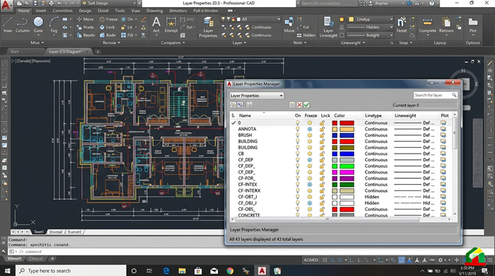
LAYER — The Foundation of Drawing Organisation
Type LAYER or LA. Opens the Layer Properties Manager — where you create, rename, colour-code, assign linetypes, freeze, lock, and delete layers.
For command-line control without opening the palette, use -LAYER. Sub-options include:
- Make — create and set current a new layer
- Color — assign a colour to a layer
- Ltype — assign a linetype
- Freeze / Thaw — hide or show layers
- Lock / Unlock — prevent or allow editing
âš ï¸ NB: Every object in a professional AutoCAD drawing must be on the correct layer — never draw directly on Layer 0 except when creating block geometry. Proper layering allows any part of a drawing to be isolated, printed, or shared independently.
LAYISO — Layer Isolate
Type LAYISO. Click an object and AutoCAD fades or locks every other layer — leaving only the selected object's layer fully visible and editable. Instantly focuses your view on one layer.
LAYUNISO — Restore All Layers
Type LAYUNISO. Reverses LAYISO and restores the previous layer visibility state in one keystroke.
LAYFRZ — Freeze a Layer by Clicking
Type LAYFRZ. Click any object and its layer is immediately frozen — hidden from view. Much faster than opening the Layer Properties Manager for a quick hide.
LAYTHW — Thaw All Layers
Type LAYTHW. Thaws every frozen layer in the drawing simultaneously — one command to bring everything back into view.
LAYERSTATE — Saving and Restoring Layer Configurations
Type LAYERSTATE. Save the current layer visibility, freeze, lock, and colour configuration as a named state — then restore it instantly at any time. Essential for drawings that need multiple presentation states — structure only, services only, finishes only.
BLOCK — Creating Reusable Components
Type BLOCK or B. Opens the Block Definition dialog:
- Name your block
- Pick an insertion base point
- Select the objects to include
The selected geometry is converted into a named block definition stored in the drawing.
💡 Tip: Create blocks for everything you use repeatedly — door swings, window types, sanitary fittings, north points, title block elements, and standard details. Every time you insert the block instead of redrawing, you save time and maintain consistency.
INSERT — Placing Blocks into the Drawing
Type INSERT or I. Select a block name, specify an insertion point, scale factors, and rotation angle. The block appears as a single object that can be moved and copied freely.
ATTDEF — Defining Block Attributes
Type ATTDEF. Creates an intelligent text field within a block — a tag that prompts for input each time the block is inserted. Used for door numbers, window references, equipment tags, and drawing revision data.
EATTEDIT — Editing Block Attributes
Type EATTEDIT. Select a block with attributes and an enhanced editor opens — allowing you to change attribute values without exploding the block.
BEDIT — Block Editor
Type BEDIT or BE. Opens the Block Editor — a dedicated environment for modifying the geometry and attributes of an existing block definition. All instances of the block in the drawing update automatically when you save and close the editor.
XREF — External Reference Manager
Type XREF or XR. Opens the External References palette for attaching, detaching, reloading, and binding external DWG files.
For command-line control, use -XREF with sub-options:
- Attach — link an external DWG as an underlay
- Detach — remove the reference
- Reload — refresh to show the latest version of the referenced file
- Bind — permanently incorporate the xref into the current drawing
âš ï¸ NB: Xrefs are the backbone of collaborative project workflows. The architect's base plan is xref'd into the structural engineer's drawing, the MEP consultant's drawing, and the interior designer's drawing — all simultaneously. When the architect updates the base plan, everyone's drawings update on the next reload. This is how large project teams work efficiently.
XATTACH — Attaching an External Reference Directly
Type XATTACH. Opens a file browser to select and attach an external DWG directly — bypassing the XREF palette for faster attachment.
XCLIP — Clipping External References
Type XCLIP. Select an xref and define a clipping boundary polygon. Only the portion of the xref inside the boundary remains visible — everything outside is masked. Perfect for showing only a relevant portion of a large site plan or base drawing.
NCOPY — Copying Objects from an Xref
Type NCOPY. Select objects within a nested xref or block and copy them directly into the current drawing — without exploding or binding the entire reference.
PURGE — Removing Unused Definitions
Type PURGE or PU. Removes unused layers, block definitions, text styles, dimension styles, linetypes, and other named objects from the drawing file. Reduces file size and eliminates clutter.
💡 Tip: Run PURGE before sending any drawing to a client or consultant. It removes internal project data that may be embedded in unused layers or block definitions — keeping your files clean, small, and professional.
AUDIT — Checking Drawing Health
Type AUDIT. Scans the drawing database for errors and repairs them automatically. The Command Line reports how many errors were found and fixed.
💡 Tip: Run AUDIT at the end of every major working session. It takes seconds and prevents small database corruptions from compounding into file-breaking problems over time.
RECOVER — Repairing Damaged Files
Type RECOVER. Opens a file browser — select a damaged or corrupted DWG file and AutoCAD attempts to repair and open it automatically. Often recovers files that appear completely broken.
REGEN — Refreshing the Display
Type REGEN or RE. Forces AutoCAD to recalculate and redraw all objects in the current viewport — smoothing out arcs that appear faceted after extensive zooming, and refreshing the display after layer changes.
Type REGENALL to regenerate all viewports simultaneously.
VPORTS — Viewport Configuration
Type VPORTS. Creates and configures multiple viewports within a layout — allowing different views, scales, and layer states to coexist on a single printed sheet.
VIEW — Saving Named Views
Type VIEW or V. Save the current display area as a named view — then recall it instantly at any time. Invaluable in large drawings where you repeatedly navigate between specific areas.
UCS — User Coordinate System
Type UCS. Redefines the working coordinate system — moving and rotating the X, Y, and Z axes to align with your geometry. Essential for drawing and editing objects that are not aligned to the standard horizontal/vertical world axes.
SAVE, QSAVE, OPEN, NEW — The Essential File Commands
SAVE— saves with a filename prompt if the file is newQSAVE— saves instantly without any prompt (Ctrl+S)SAVEAS— saves a copy under a new name or locationOPEN— opens an existing file (Ctrl+O)NEW— starts a new drawing, optionally from a template (Ctrl+N)
âš ï¸ NB: Develop the habit of pressing Ctrl+S every few minutes without thinking about it. AutoCAD's auto-save is a backup — not a substitute for regular manual saving. The professionals who never lose work are the ones who save constantly.
🧱 SECTION 7: 3D Modeling Commands — Building in Three Dimensions
AutoCAD is far more than a 2D drafting tool. Its 3D modeling environment allows architects, engineers, and product designers to build precise three-dimensional geometry — from simple solid primitives to complex swept and revolved forms. This section introduces the 3D command set.
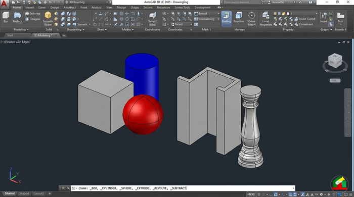
The Solid Primitives — Building Blocks of 3D
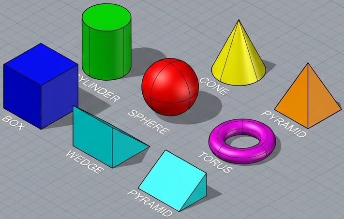
These commands create the fundamental 3D solid shapes from which more complex forms are built:
BOX — Type BOX. Specify a first corner, then the opposite corner (or length and width), then a height. Creates a rectangular solid.
CYLINDER — Type CYLINDER. Specify a centre, radius, and height. Creates a perfect circular column or tube.
SPHERE — Type SPHERE. Specify a centre and radius. Creates a perfect sphere.
CONE — Type CONE. Specify a base centre, radius, and height. Add a top radius to create a truncated cone (frustum).
WEDGE — Type WEDGE. Prompts mirror the BOX command — creates a right-angle triangular solid.
TORUS — Type TORUS. Specify a centre, the ring radius (centre to tube centre), and the tube radius. Creates a donut-shaped solid — perfect for pipe bends, rings, and circular mouldings.
PYRAMID — Type PYRAMID. Specify the number of sides, base dimensions, and height. Add an apex radius for a truncated pyramid. Creates roof forms, structural pylons, and decorative elements.
💡 Tip: All 3D primitives are created as ACIS solids — fully editable, Boolean-capable objects. They are the starting point for almost every 3D model in AutoCAD.
EXTRUDE — Pushing 2D Profiles into 3D
Type EXTRUDE or EXT. Select a closed 2D boundary (polyline, circle, rectangle), then specify:
"Specify height of extrusion or [Direction/Path/Taper angle]:"
- Height — straight vertical extrusion
- Direction — extrude along a vector between two points
- Path — extrude along a curve (pipe along a path)
- Taper angle — extrude with a draft angle — walls that lean inward or outward
💡 Tip: EXTRUDE is how 2D floor plans become 3D building models. Draw your floor plan as closed polylines, extrude each wall to storey height, and your building takes shape in minutes.
REVOLVE — Rotating Profiles Around an Axis
Type REVOLVE or REV. Select a 2D profile, then define a revolution axis with two points, and specify the angle of revolution (up to 360°).
💡 Tip: REVOLVE is perfect for columns, vases, turning profiles, domes, and any form with rotational symmetry. Draw the profile as a 2D cross-section, revolve it 360°, and the solid appears instantly.
SWEEP — Following a Path
Type SWEEP. Select a 2D cross-section profile first, then a path curve. AutoCAD sweeps the profile along the path — maintaining orientation and creating a continuous solid.
Sub-options include:
- Alignment — align the profile perpendicular to the path
- Base Point — control where on the profile the path attaches
- Scale — taper the profile along the path
- Twist — rotate the profile as it travels along the path
💡 Tip: SWEEP is the command for handrails, pipe runs, cable trays, curved beams, and any element that follows a non-straight path. Define the pipe's circular cross-section and sweep it along a routed path — one command, perfect geometry.
LOFT — Morphing Between Cross-Sections
Type LOFT. Select two or more cross-sectional profiles in sequence. AutoCAD creates a solid that morphs smoothly between them. Options include:
- Path — a guide curve controlling the overall shape
- Guides — multiple curves constraining the surface
- Cross-sections only — AutoCAD interpolates freely
💡 Tip: LOFT is the command for complex organic forms — tapered building facades, boat hulls, aircraft components, and terrain models. It handles shapes that no other solid command can produce.
UNION — Combining Solids
Type UNION or UNI. Select two or more solids and AutoCAD merges them into a single unified solid — removing all internal boundaries.
SUBTRACT — Cutting Solids Apart
Type SUBTRACT or SU. First select the solid(s) to subtract from, press Enter, then select the solid(s) to subtract away. AutoCAD removes the subtracted volume — creating holes, recesses, and cutouts.
💡 Tip: SUBTRACT is how you cut door and window openings in wall solids, drill bolt holes in flanges, and carve structural voids in slabs. Draw the cutting shape as a solid, position it correctly, then subtract.
INTERSECT — Keeping Only the Overlap
Type INTERSECT or IN. Select two or more overlapping solids and AutoCAD retains only the volume where they overlap — discarding everything else.
FILLETEDGE — Rounding 3D Edges
Type FILLETEDGE. Select edges on a solid and specify a radius. AutoCAD rounds the selected edges with a smooth fillet — adding realism and removing sharp corners from 3D models.
CHAMFEREDGE — Bevelling 3D Edges
Type CHAMFEREDGE. Select edges on a solid and specify distances. AutoCAD cuts a flat bevel along the selected edges.
3DMOVE — Moving Objects in 3D Space
Type 3DMOVE. Works like MOVE but displays a 3D gizmo — coloured axis arrows — allowing you to constrain movement to the X, Y, or Z axis by clicking the corresponding arrow.
3DROTATE — Rotating Around a 3D Axis
Type 3DROTATE. Displays a coloured rotation gizmo — click the X, Y, or Z rotation ring to constrain the rotation axis, then specify the angle.
3DALIGN — Aligning Objects in 3D
Type 3DALIGN. Define three source points on the object and three corresponding destination points. AutoCAD moves and rotates the object to align source points with destination points — handling full 3D transformation in one step.
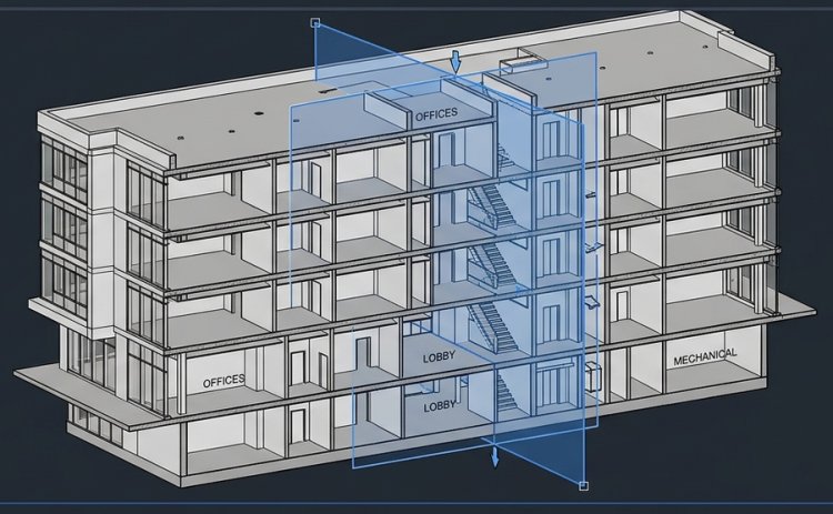
SECTIONPLANE — Live Section Cuts
Type SECTIONPLANE. Create a section plane through a 3D model that displays a live cut — revealing internal geometry. The section plane can be jogged for multi-level sections and can generate 2D section drawings automatically.
FLATSHOT — Generating 2D Views from 3D Models
Type FLATSHOT. Projects the current 3D view into a 2D block — creating accurate plan, elevation, and section views from your 3D model for use in 2D drawing sheets.
MASSPROP — Physical Properties of Solids
Type MASSPROP. Select a 3D solid and AutoCAD calculates and reports:
- Volume
- Surface area
- Centroid (centre of mass)
- Moments of inertia
- Principal moments and axes
💡 Tip: MASSPROP is invaluable for structural and mechanical engineers verifying section properties, calculating material volumes for cost estimates, and checking design compliance against physical criteria.
🔠What's Coming in Part 3
You now have the complete command vocabulary of AutoCAD — from the first line to full 3D solids. But knowing what commands exist is only half the battle. The next stage is putting them together in a real workflow.
In Mastering AutoCAD (Part 3), we apply these commands to a real project:
- ðŸ Drawing a complete architectural floor plan from scratch
- 📠Setting up layers, line types, and drawing standards
- ðŸ-¨ï¸ Configuring Paper Space layouts for professional printing
- 📠Dimensioning and annotating to industry standards
- 💾 Setting up drawing templates for future projects
💡 Tip: Before Part 3, open AutoCAD and spend time practising the commands in each section of this article. Do not try to memorise them — just use them. The Command Line will guide you through every step. Repetition builds the fluency that transforms a tool into a skill.
🚀 Final Thoughts
Over 130 commands. Seven categories. One coherent language.
AutoCAD is not a collection of isolated buttons — it is a conversation. Every command you type starts a dialogue. The prompt tells you what it needs. You answer with coordinates, distances, selections, and keywords. The geometry appears.
The professionals who work fastest in AutoCAD are not the ones who memorised the most commands. They are the ones who listen to the prompt most carefully — who trust the dialogue, answer precisely, and let the software do exactly what it was designed to do.
You now have the vocabulary. In Part 3, we build something real with it.
Follow the Mastering AutoCAD Series on The Homes Lab Community — and share this article with every architect, engineer, designer, or student you know who is learning AutoCAD.